Houdini Procedural Bookshelf Tutorial
Download the Example FIle for a closer look.
However if you are learning I highly recommend setting this up yourself and then checking your work with the file
This is a simple setup for a procedural bookshelf in houdini.
Obviously there are infinite ways to set this up, this is just the way I decided to do it
I am going to set this up so it’s easy to expand with more features down the road.
# Initial Setup and Prep
For this setup we are going use a point based workflow.
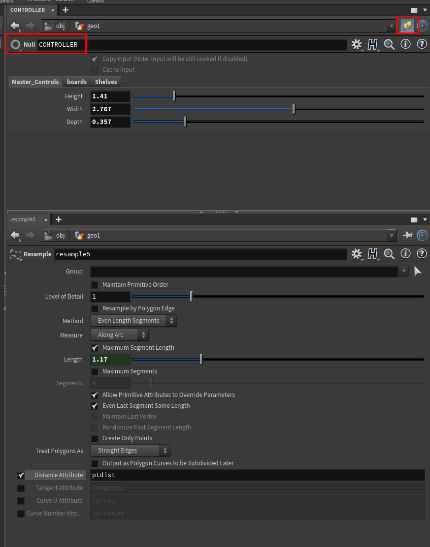
First drop down a null and call it CONTROLLER or something like that.

You can hit
Cto bring up the color palette andZto bring up the node shape palette to make the node look like the above.
This
nullcontroller workflow is very helpful once we get into Houdini HDAsand tool building.Houdini HDAs
Houdini HDAs, also known as digital assets are used to package up nodes for reuse in convenient ways. You can think...
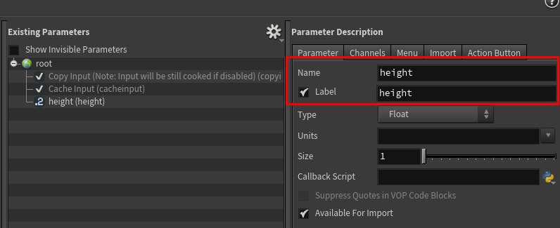
Right away, we already know we will want to control some of the main parameters of this bookshelf:
- Height
- Width
- Depth
And a few others you will see below
So let’s add those to the parameters on the null.
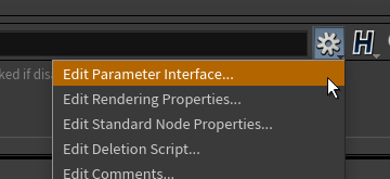
To access the parameters on any node including this null click on the gear icon in the parameters window an select
edit parameter interface
There are many ways to add parameters. But for now just drag over from the list into the middle window.
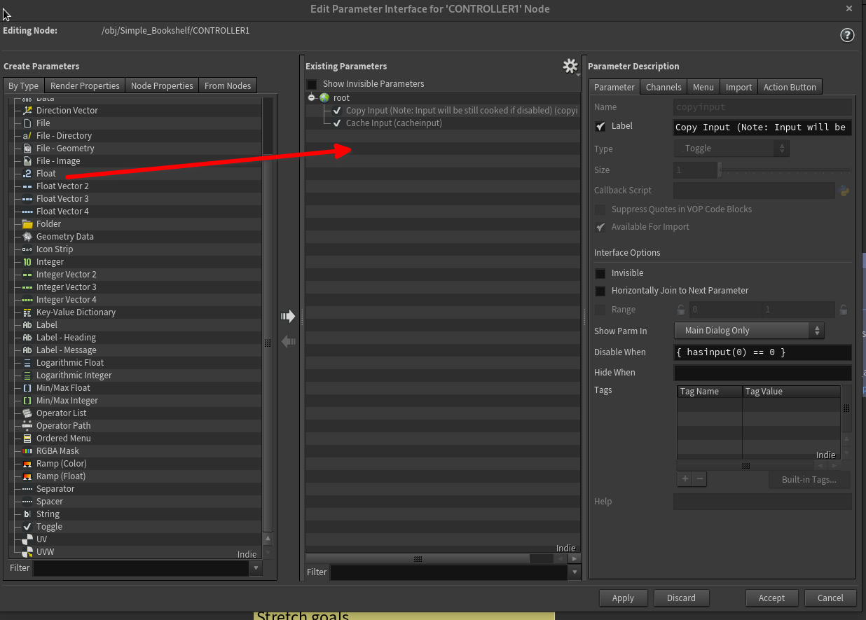
Then make sure you have named the parameter correctly.
the two fields that I have named the same actually serve different purposes. The label is what you see in the interface. The name is it’s ID under the hood. This is important if you end up scripting with python and need to target a parameter. I think it’s a good habit to make them the same for now.
You could also add a folder called master controls or something like that to keep your interface organized.
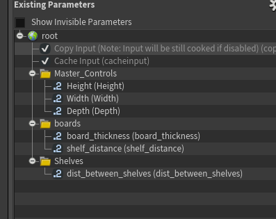
Go ahead and add the following parameters:
# First Nodes Setup
For now let’s set this up with a line at first.
# First line Node
- Drop down a
linenode. - Set the direction to be left or right not up or down.

This will determine the total width of the bookshelf.
# Controller Node
Now let’s start using our controller.
# Copy Parameters from Controller
First, right click on the width (or whatever you named it, it should be the length or width of the bookshelf) parameter and select copy parameter.
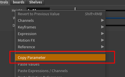
Then on the line node right click on the lenght parameter and select paste relative references.
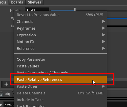
Now the lines length will be controlled by the slider on your controller.
I often work with two parameter windows open when I do controllers. One I pin to the controller and the other will follow my selection.
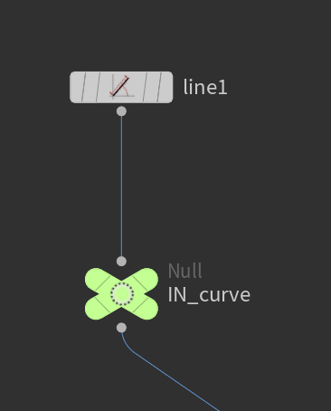
# Null IN node
Next you can drop down a
null. I named itIN_curve. This is just so in the future we have a clear input point and if we want to upgrade our setup we can.
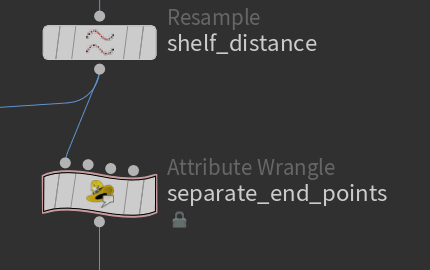
# First Resample Node
Next, drop down a resample node.
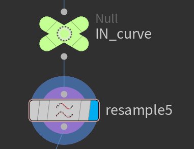
This will determine the distance between the separator boards.
Check the Resample Node Documentationfor more info. The resample node splits up line segments by distance or amount.
We need to check one box on the resample node:
Distance Attribute
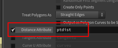
This will help us determine the length of the boards later in the stream.
Houdini attributes are data that can be attached to points, verts, prims, or the whole object (detail). For more info refer to the documentation Geometry attributesWe will be using attributes and groups in this lesson.
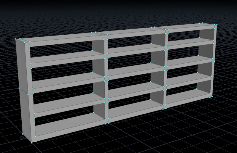
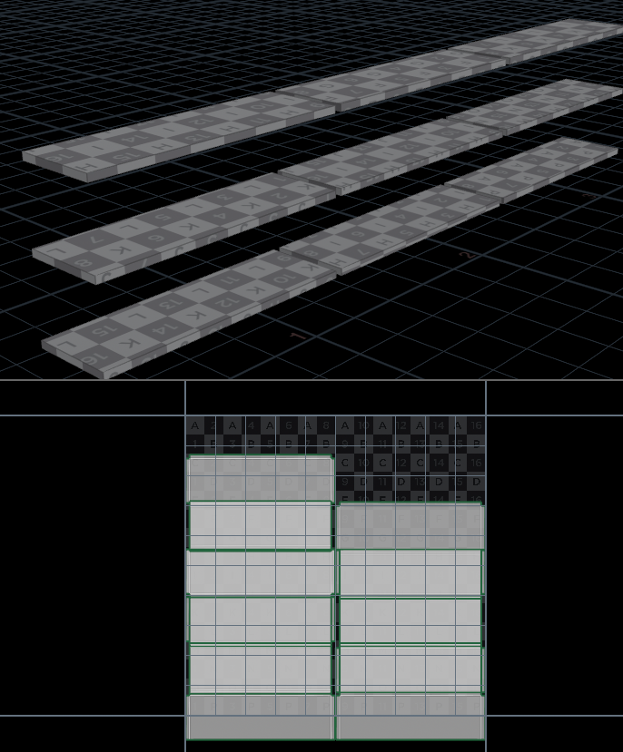
# Bookshelf Components
Ok we now have the foundation set for the rest of the setup.
let’s outline the components and how we want them to behave:
Components:
- End vertical boards
- Intermediate separator boards
- Shelves
- Top board
These should automatically generate with the size of the bookshelf and the parameters we set for separation between shelves and separators.
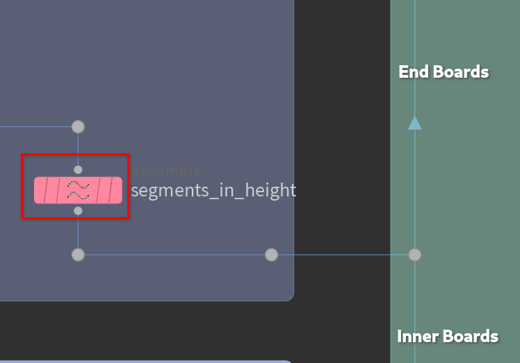
# End boards
These boards will be mark the ends of our bookshelf.
# Separate end points with wrangle
So we have the resampled line. We will be using a copy to points node to put the pieces where we want them. So we will want to separate out the the first and last points. The easiest way to do this is in a point wrangle with vex.
Don’t worry if you don’t understand the vex yet. I’ll do my best to explain. It’s not too scary.
In the node copy the following code:
| |
Here is an explanation of the code:
#code-explanation
1int npts = npoints(0)-1; // npoints is the total number of points in the geo stream
- The variable
nptsis declared as an integer and assigned the value of the total number of points in the geometry stream (0).- The
npoints()function returns the number of points in the stream, and by subtracting1, the variablenptsrepresents the index of the last point in the stream.
1int firstPoint = 0;
- The variable
firstPointis declared as an integer and assigned the value0.- This variable will be used to store the index of the first point in the stream.
1vector firstPosition = point(0, "P", firstPoint);
- The variable
firstPositionis declared as a vector.- The
point()function retrieves the position (“P”) of the point at indexfirstPointin the geometry stream (0).- The retrieved position, a three-dimensional vector representing the coordinates of the point in 3D space, is assigned to the
firstPositionvariable.
1setpointgroup(0, "firstlast", firstPoint, 1);
- The
setpointgroup()function is called to set a point group named “firstlast”.- The arguments provided to the function are the geometry stream (
0), the name of the point group (“firstlast”), the index of the point (firstPoint), and a value of1.- This effectively adds the
firstPointto the “firstlast” point group.
1
2
int lastPoint = @numpt - 1; @lastpnt = lastPoint;
- The variable
lastPointis declared as an integer and assigned the value of the attribute@numpt(the total number of points in the current geometry).- By subtracting
1,lastPointrepresents the index of the last point in the stream.- The
@lastpntattribute is then set to the value oflastPoint.
1vector lastPosition = point(0, "P", lastPoint);
- The variable
lastPositionis declared as a vector.- The
point()function retrieves the position (“P”) of the point at indexlastPointin the geometry stream (0).- The retrieved position is assigned to the
lastPositionvariable.
1setpointgroup(0, "firstlast", lastPoint, 1);This line adds the
lastPointto the “firstlast” point group using thesetpointgroup()function.In summary, this code retrieves the positions of the first and last points in a geometry stream and stores them in
firstPositionandlastPosition, respectively. Additionally, it adds the first and last points to a point group named “firstlast”.
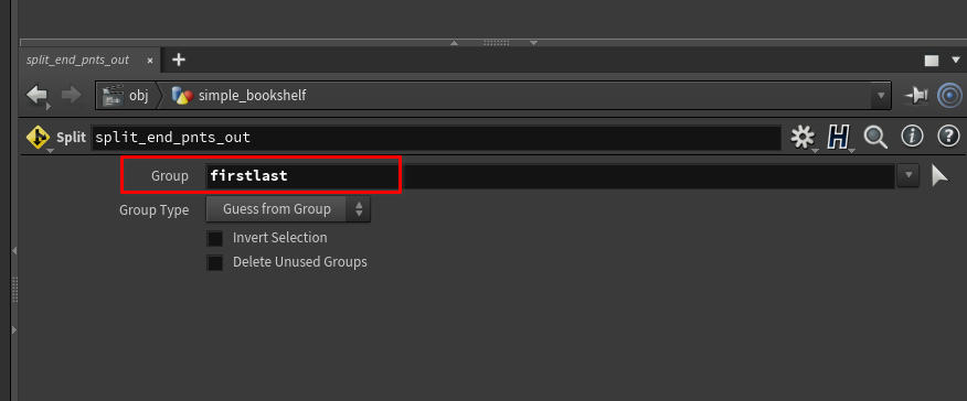
# Split node to split out the end points
Next we will drop down a split node.
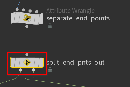
This will split the geo-stream by group. We created a group in the wrangle so now we will use it here.
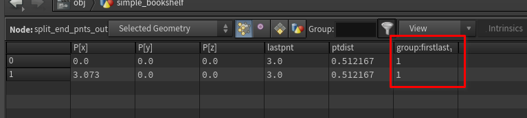
Checking for groups
There are a few ways you can check for attributes and groups on any node.
- Middle click on a node to bring up the node info. This will show all the data about that node.
- Hover over a node till the
node ringshows up
- Click on the
i
This will bring up the info window:
The other way is checking the
geometry spreadsheetThe spreadsheet will show all the data for any node selected.
There is a lot to learn about the
geometry spreadsheet, check the documentation for more info -> Geometry Spreadsheet pane

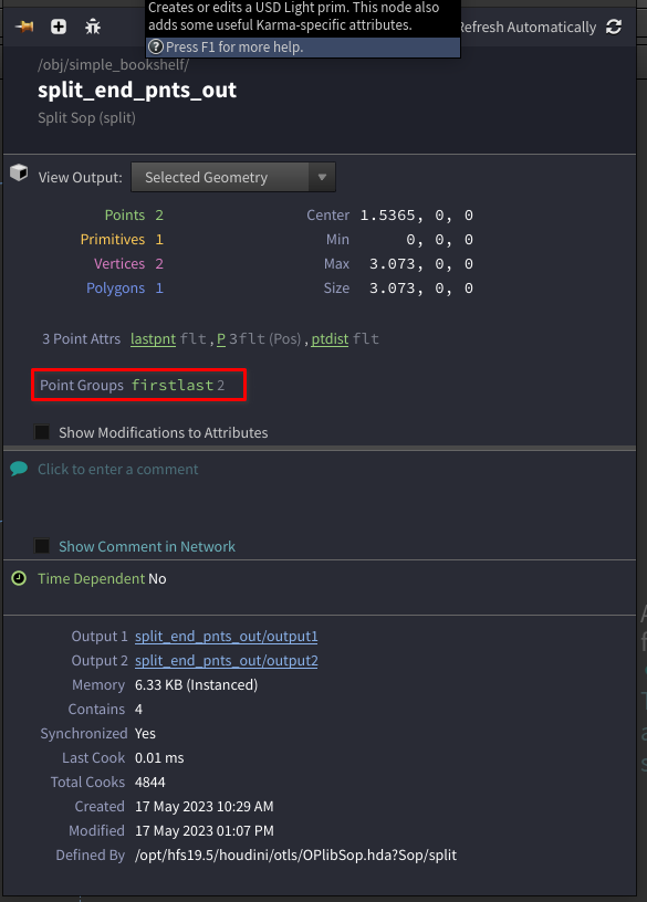
Now the stream is separated between the first and last points and the ones in the middle.
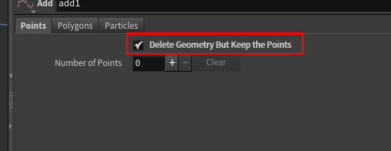
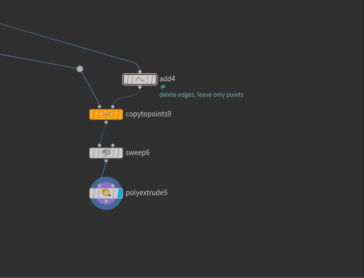
# Add node to remove edges
The next thing I’m going to do it wire-in an Add node to output of the split that just has the ends.
This is just to clean things up.
On the add node I’m going to check Delete Geometry But Keep Points
This is where things start to get a little more complex.
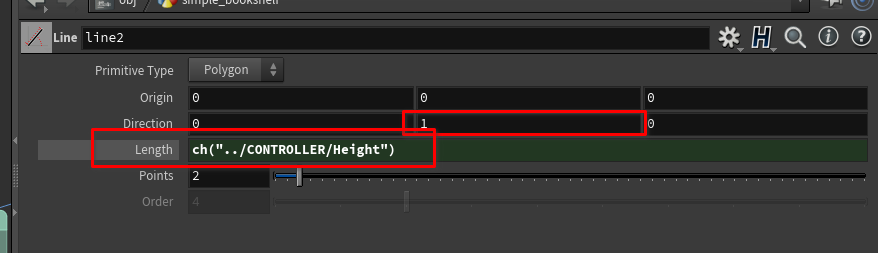
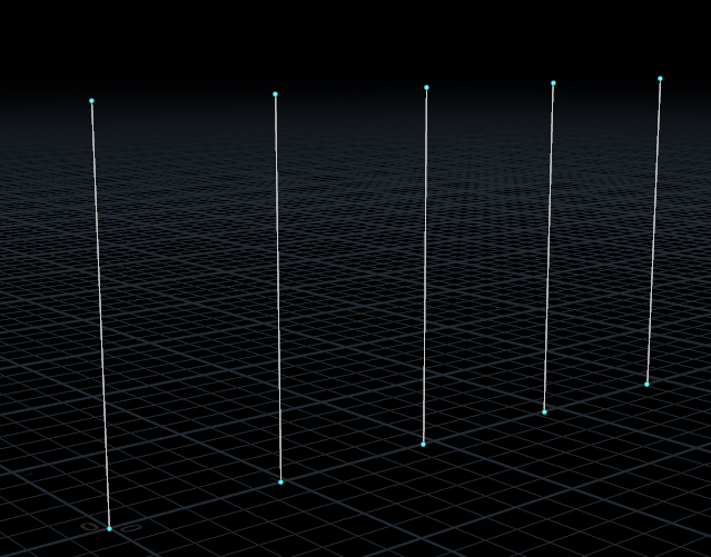
# Second Line node for height
Next we want to drop down another line node.
This line should be facing upwards on the Y axis and we should copy out height parameter into the length of the line.
This line will be height of our bookshelf!
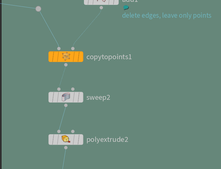
# Copy to points for the end boards
Next we will drop down a Copy to Points node.
The
Copy to Pointsnode will allow us to copy anything to any points we feed into it.
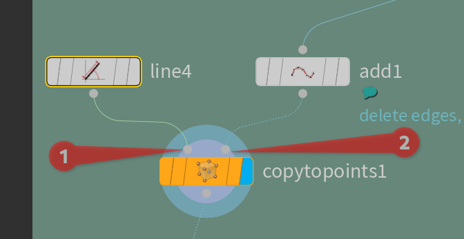
- geometry to copy
- points to copy to
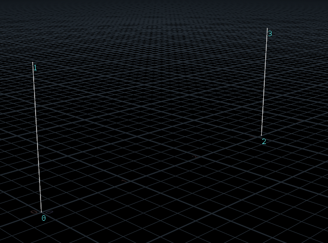
Now you should have two lines pointing up like so:
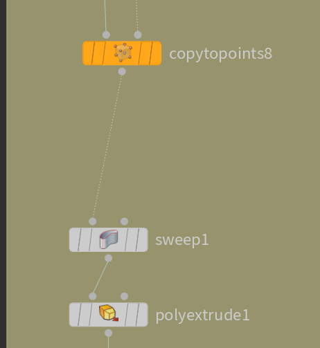
# First Sweep Node
Next let’s drop down a
Sweep node. and wire it into the output of the copy to points.
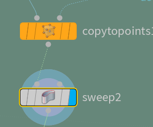
There are two parameters on the sweep node we need to worry about.
- Surface Shape
- Width
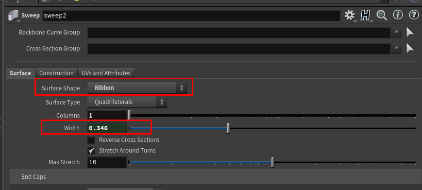
- Change the surface shape to ribbon.
- Then change the columns to
1.
Ribbon will make it so houdini creates quads that follow the input curve.
Copy in our Depth parameter from the CONTROLLER into the width parameter on the sweep node.
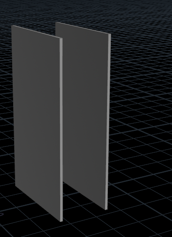
Now you should be able to control the height, width, and depth of the ends like so:
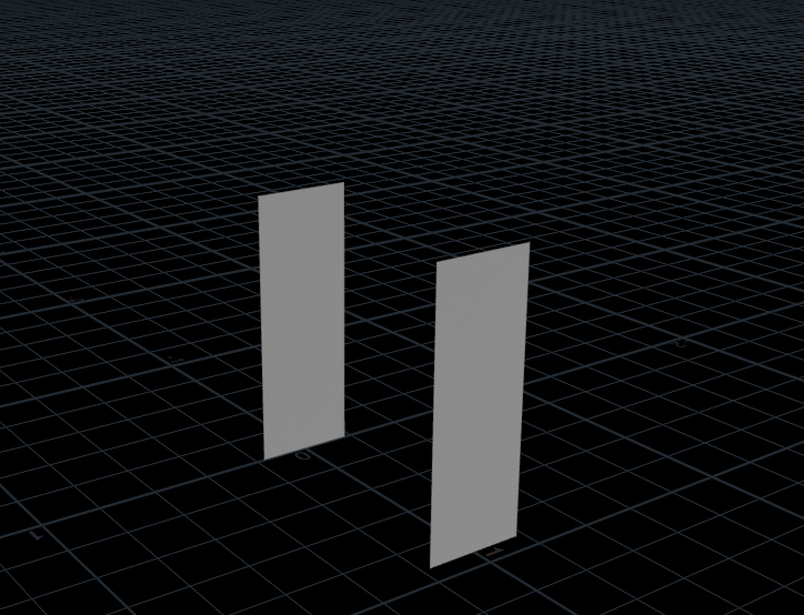
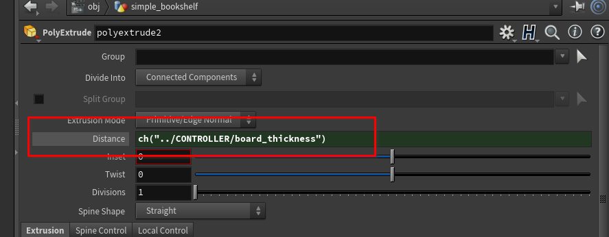
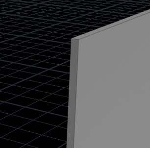
# Extrude end boards
Next we’ll drop down a
Poly Extrude node and wire it into the output of the sweep node.
The
poly extrudenode will extrude just like in other 3D packages.
This is how we will get thickness in our boards.
The only parameter we care about here is Distance. We will reference our Board Thickness parameter from our CONTROLLER here.
It should now look like this:
Organizing the network
You can create a frame around selected nodes by pressing
SHIFT+O
Your network should look something like this now:
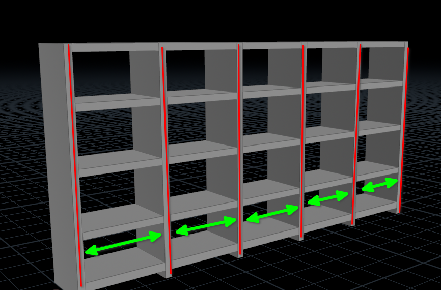
# Bottom Boards
# Horizontal line
Next we will create another line node.
Wire in a null into the lines output and call it OUT_horizontal_line.
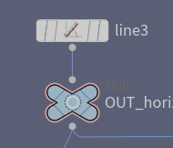
I put this line in another frame for setup objects, because we will reuse this line for more components.
# Copy to points boards
Drop down a new copy to points node.
Now connect the OUT of the new line to left side of the new copy to points node.
Now wire in the output of the first resample node into the right input of the new copy to points.
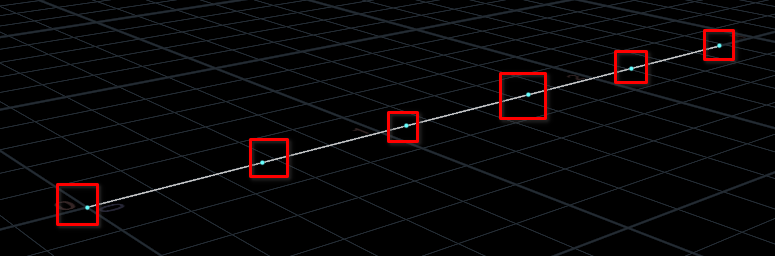
You’ll probably notice there is a problem. The lines extend past the edge of the bookshelf. So let’s fix this:
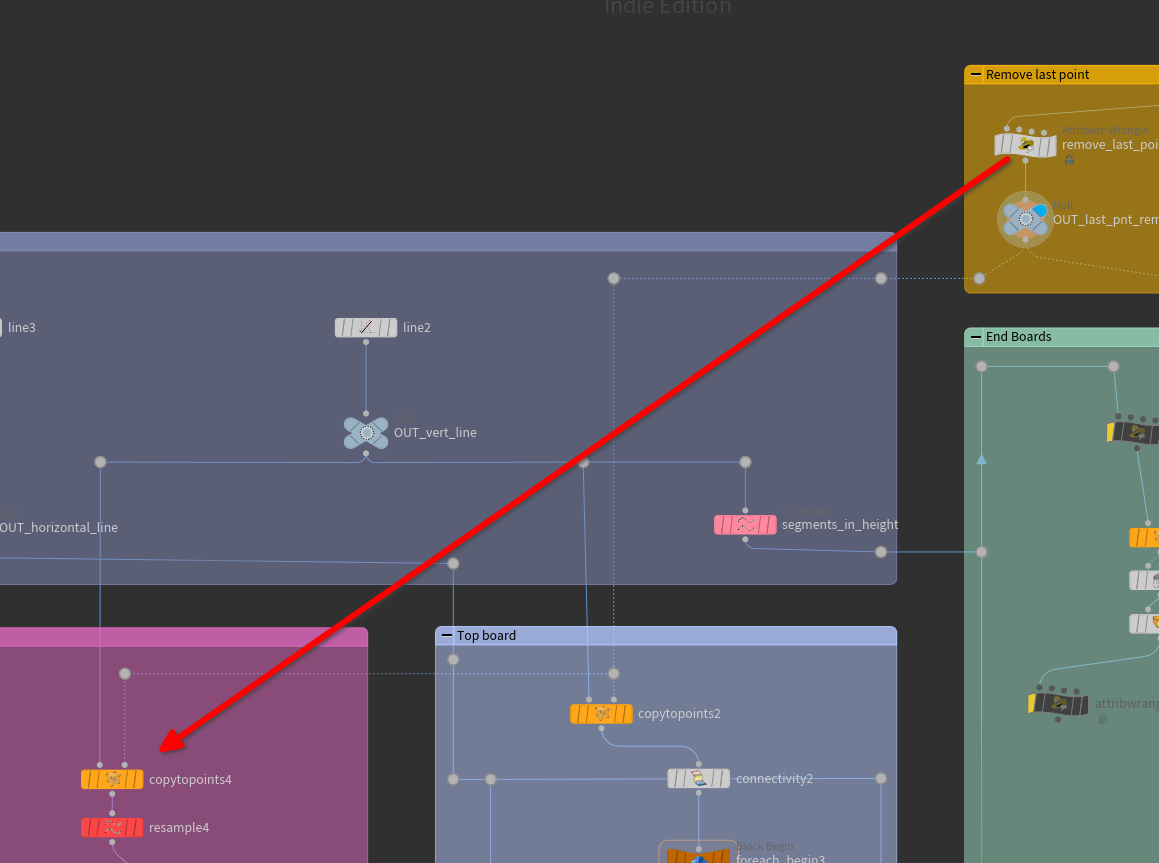
# Remove last point wrangle
Between the first resample and the boards copy to points we just put down, drop down a new attribute wrangle.
Copy this code into it:
| |
This will remove the last point in the array.
Now it doesn’t extend past the edge.
# Board Geo
This part is easy. Just copy the sweep and poly extrude nodes you made before.
You can copy nodes with
CNTRL+Cand paste withCNTRL+VOR holdALTand drag nodes and they will copy.
Copying these nodes will ALSO copy the references inside them so you don’t need to set it up again.
Now let’s add a transform node below those two and set an offset of 0.05 in the Y direction to move them up a bit.
# Vertical Separators
You’ve probably noticed that the bottom boards aren’t the correct length. This will get a little more complicated than before, so follow along closely.
There are a few things we need to do to fix this.
This is where we will use the
ptdistattribute we turned on in the resample node.
# Creating the vertical boards
Firs thing we’ll do is copy the entire copy to points sweet poly extrude chain from before.
Then we wire in the vertical line we made into the left slot of the copy to points.
Next, take the right output from the split node and wire it into the right side of the new copy to points node.
You should have one or more vertical boards like this:
# ptdist attribute
The reason I am using the
ptdistattribute instead of just theLengthparameter from theresamplenode is for two reasons:
- What if I don’t want to use the
lengthparm and instead want to use amount?- The
Lengthresults in some wiggle room and imprecise distances as things change. For this we need precision.
One of the problems we have to solve is how do we get the information of the distance between points to the line distance and anywhere else we need it.
We will drop down 3 nodes:
Attribute PromoteAttribute Wranglenull
Hook them up respectively.
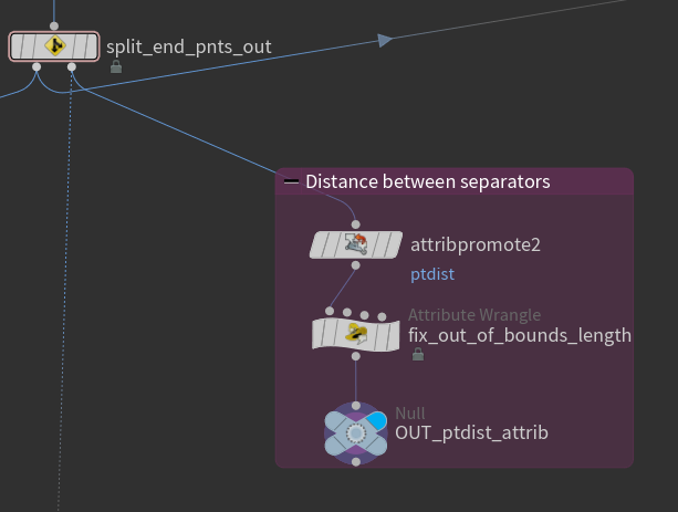
# Attribute Promote
The first node is an attribute promote, This node lets up change type of an attribute. In our case we just need to worry about two fields.
original namenew class
set ptdist in the first one. and set the new class to Detail
Detailattributes are not stored on components but instead on the object level. We only need this stored once, so we save computation by not putting it on points.
# Attribute Wrangle
In this wrangle we will solve a strange behavior that caused me some problems. The problem was that because we were using the distance attribute when there was no extra points being created in the resample that attribute was set to 0. So we need to correct it.
What we will do is check whether the attribute is zero, if it is we will set it to the length of the bookself.
| |
To create a parameter in vex you use channel expressions. In this case
chfstands for channel float. or a float channel. The argument is a string indicating the name it will have. Then you click the slider button in the wrangle.
Now copy in the length parm from the CONTROLLER into the new parameter.
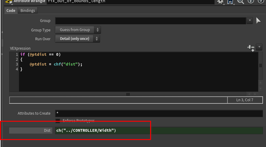
Now name the null something like OUT_ptdist.
# Shelves
Now we will use the ptdist attribute. In this case we will use an expression inside a parameter.
Houdini uses
HScriptorPythonas an expression language. HScript is similar to linux command line languages likeBash. You can check the documentation for more info Expression functions
In the horizontal line node we created earlier is where we will write this expression.
In this case I am using
HScript
The expression is:
| |
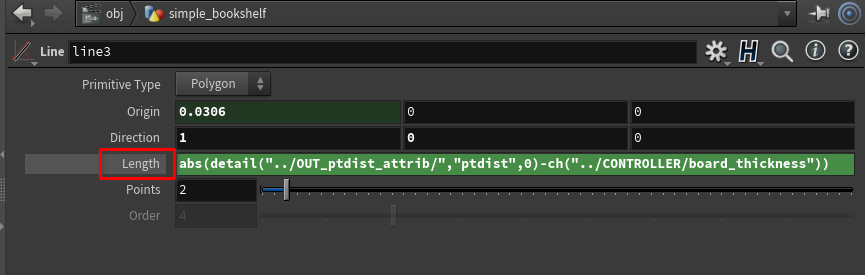
abs()is a function that calculates the absolute value of a number. It ensures that the result is always positive.detail()function is used to access attribute values from another geometry in the scene. In this case, it is accessing the attribute named “ptdist” from the geometry located at the relative path “../OUT_ptdist_attrib/”. The third argument,0, specifies that the first geometry instance should be used."ptdist"is the name of the attribute being accessed using thedetail()function. It refers to the attribute called “ptdist” in the referenced geometry.-is the subtraction operator, which subtracts the value obtained fromdetail("../OUT_ptdist_attrib/","ptdist",0)from the next part of the expression.ch()function is used to retrieve the value of a channel parameter. In this case, it is accessing the channel parameter named “board_thickness” from the node located at the relative path “../CONTROLLER/”."../CONTROLLER/board_thickness"specifies the relative path to the channel parameter named “board_thickness” in the referenced node.
Putting it all together, the expression calculates the absolute difference between the value of the ptdist attribute from the referenced geometry and the value of the “board_thickness” channel parameter from the referenced node. The abs() function ensures that the result is positive.
Now we just need to copy the parameter board thickness from the CONTROLLER into the X component of the origin vector on the line.
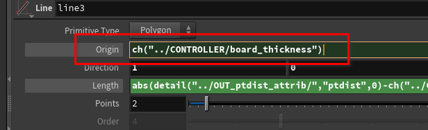
What this does is shifts the line over based on the thickness of the boards and shrinks it so that there are no intersections.
This will be important if we want to destroy the bookshelf.
# Loops
Next we will use loops in the SOP network.
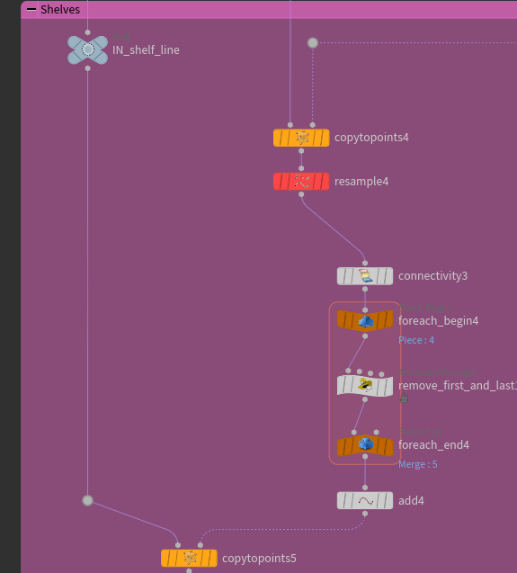
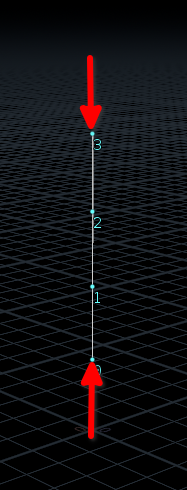
The reason we are going to a loop here is simple. We need to delete first and last point of each shelf line. This is to remove to the top and bottom lines because those are already accounted for in the rest of the network.
We can drop down a for each connected piece loop preset. This will setup a connectivity node which adds a class attribute to each separate piece. We can then loop through each of those separately.
The reason we use a loop is to easily solve the the first and last in each line. This is because we are going to use the point numbers to target the first and last in a wrangle.
Before we get to the loops though we need to drop down a copy to points. This will copy the lines we will use for the shelves.
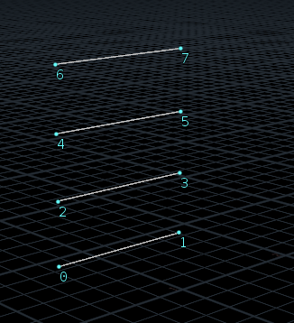
Below is sort of what the lines should look like (depending on your parameters)
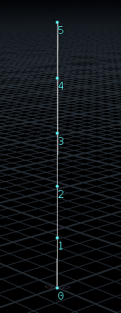
After the copy to points drop down a resample node.
The resample node will determine the amount of shelves in our bookshelf.
In the resample we’ll then copy the shelf_distance to length.

Now your lines should look similar to this:
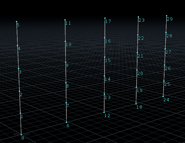
Pay attention to the numbers here. As explained before we will have to use this information to solve a problem.
Now is where we get into loops.
Loops are pervasive in programming, in houdini we can use loops on the SOP level to loop through elements of the geometry or simply sumbers.
Drop down a loop through connected pieces loop preset. This will create a set of nodes that will loop through separate pieces of a mesh.
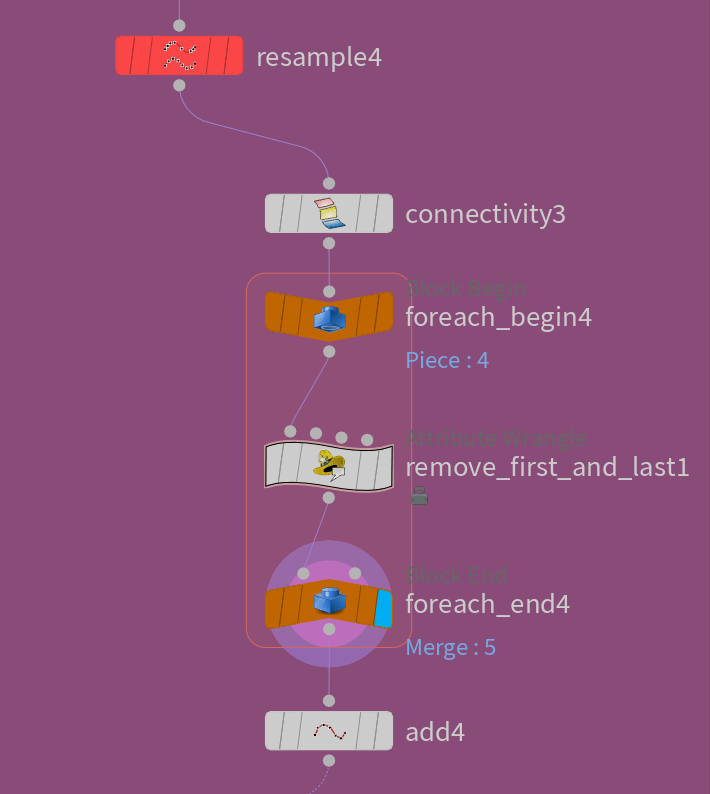
Next put an attribute wrangle inside the loop and add the following code to it.
Make sure you are running over points
| |
If you turn on single pass in the foreach loop we can see what’s going on. Each line now has point numbers that start at 0.
After the wrangle it looks like this:
Now we take the horizontal lines and copy those to these points.
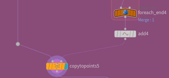
It should look similar to this now:
Now we do the same thing we did for the rest of the boards. We use a sweep and polyextrude node.
In the sweep node copy in the depth parameter from the controller. Or whatever parameter you are using for the depth of the bookshelf.
Then in the polyextrude node copy in the board thickness parameter from the controller to the Distance parameter of the polyextrude node.
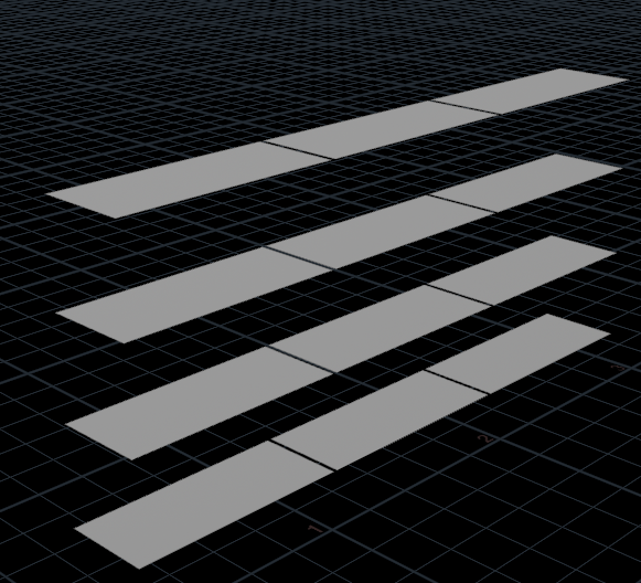
You should now see the following in the viewport:
# Top Board
Remember we removed the top and bottom boards. Now we need to add them back in.
We will do this in a similar way.
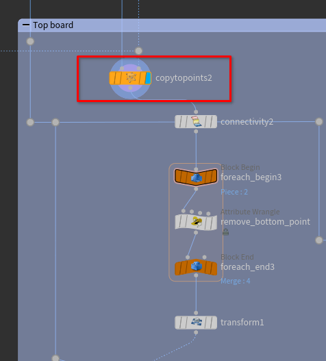
Next we need to plug in the horizontal and vertical lines into this copy to points. It should look like the following:
Next we need to drop down another Loop through connected pieces, just like before.
Now put an attribute wrangle down inside the loop. This time all we need to do is remove the first point. We can do so with one line:
| |
Now after the loop drop down a transform node.
In the Y section of the transform copy the Board Thickness parameter and add a - to the front.
This will offset the lines by the board thickness in the Y direction.
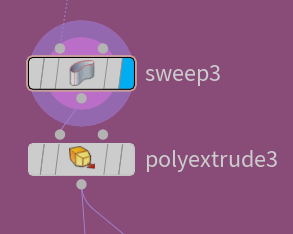
Next add the sweep and poly bevel nodes like before.
You can copy them from the other setup because the references are going to be the exact same here.
# Combine components
Now we can combine all the components.
Drop down a merge node and pipe in all the OUTs from each component into it.
It should look like the following:
# UVs
Let’s tackle procedural UVs. This can be an extremely complex topic, we are going to keep it as simple as we can to make doing it procedurally worthwhile for us.
# Defining the problem for UVs
In procedural systems where the geometry changes and we want textures or surface coordinates we need our UV system to be procedural as well.
To accomplish this we will start with a simple solution.
Procedural UVs can be tricky and computationally intensive.
# Setting up initial UVs
Now in each of the blocks we’ve created for all our components we will need to add a section for UVs.
First let’s add a UV section to our controller. In that section let’s add a toggle parameter and name it bypass UVs.
Now, in each of the component sections add the following after the polyextrude nodes.
uvautoseamuvflattenswitch
Hook the switch node up to bypass the UV nodes.
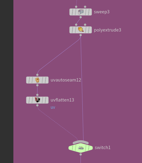
copy the bypass UVs parameter into the switch node. This will allow us to bypass the UVs while we are just working on the geometry.
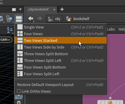
You can split the 3D viewport by using the white square drop-down in the top right.
Your UVs should look something like this:
# Fixing UVs for vertical boards
Once you have copied this setup to the other components you’ll probably notice that the UVs for the vertical boards are not consistent. They are too long and force the rest of the UVs to be too small or are not the correct texel density.
In order to fix this we need to add edge loops to our geometry. This will allow us to cut the UVs so they fit in our UV space better.
To do this we need to add a resample node after the OUT_vert_line and before the inner and outer vertical boards.
Let’s add another parameter to our CONTROLLER. Add a float called vertical_board_UV_split to the UV section we created.
Copy that parameter into the distance of the new resample node we created.
We are using a resample here because the
sweepnode will create segments at each point. It’s easier doing it this way than adding edge loops after the fact.
Now add a group node after the polyextrude. It should look like this:
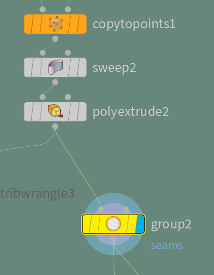
This will allow us to select those edge loops. In the group node uncheck everything but include by edges and then only have max edge angle checked on. and set it to 20
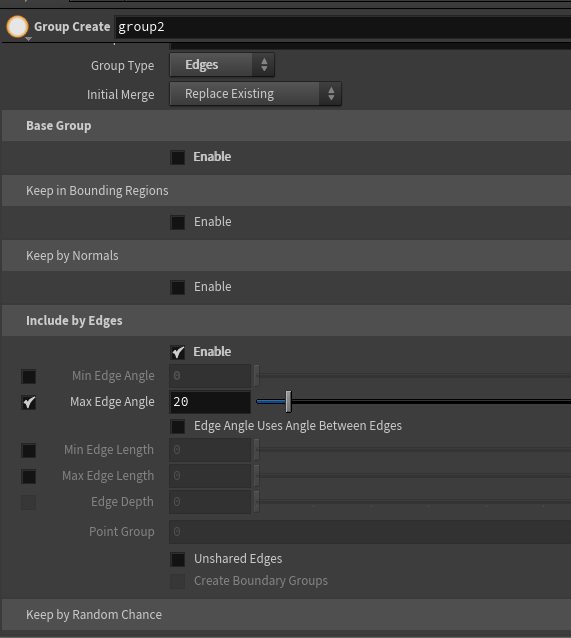
Name the group seams.
Now the UV nodes and the switch should be copied over after this group node.
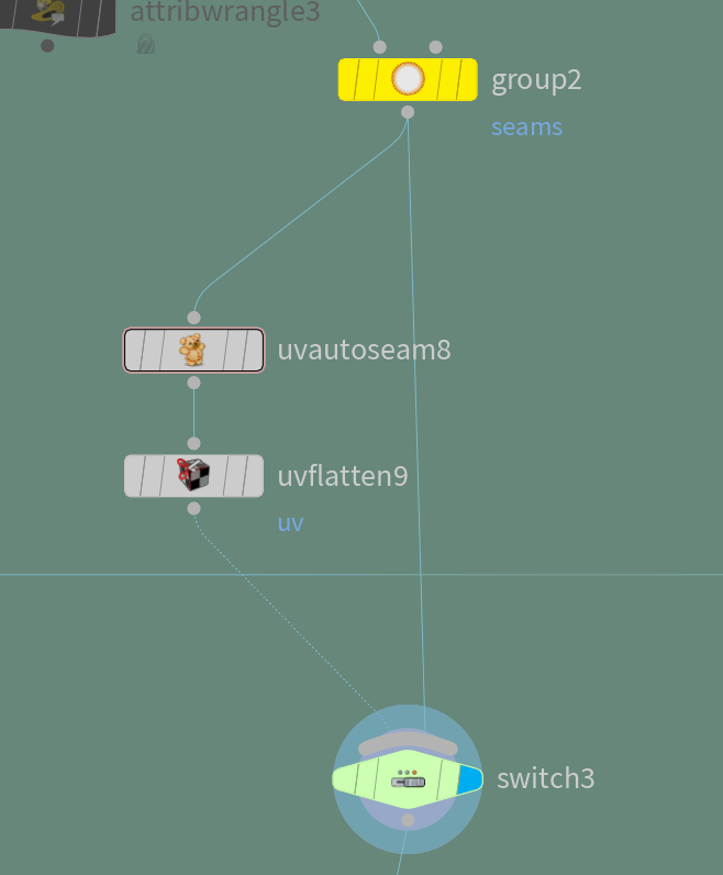
In the uvautoseam we need to tell it to use the group we just created as seams to cut the UVs.
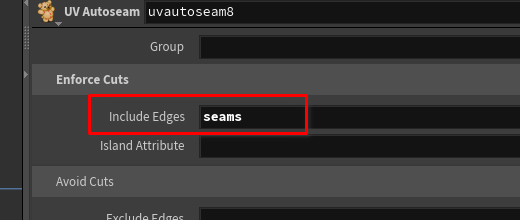
Add the seams group to the include edges parameter of the uvautoseam.
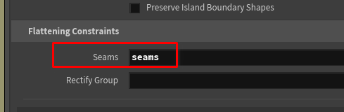
Then add the seams group to the uvflatten node under the Flattening Constraints and in the seams parameter:
Now you should have something like the following:
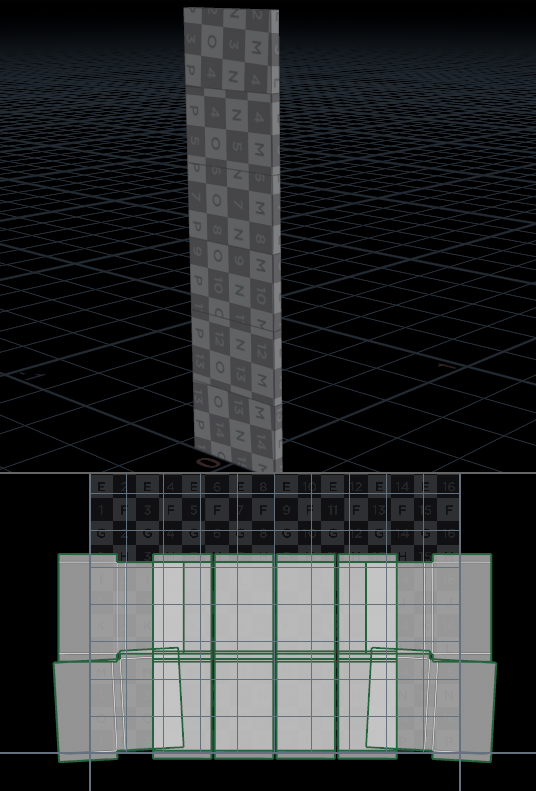
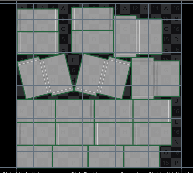
We can see the cuts here working as expected and unwrapping the geometry.
But we have overlapping UVs. We need to add the seams group to another parameter in the uvflatten node.
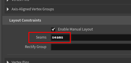
Add seams under the layout constraints section in the seams parameter.
Now our UVs should look like this:
# UV layout
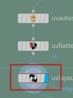
We now want to layout the UVs a bit better. we can do this with a uvlayout node. Let’s drop one after the uvflatten node.
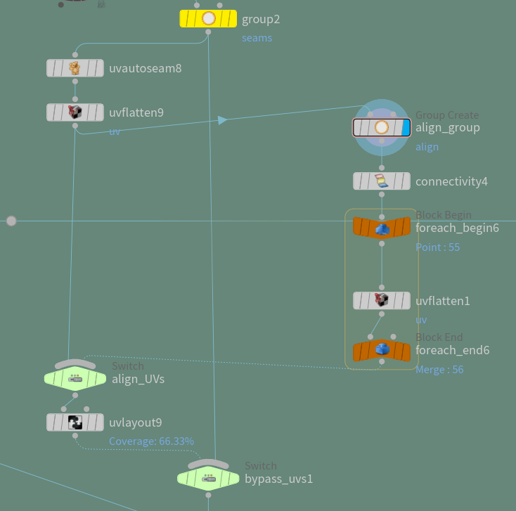
Next let’s add a toggle to our CONTROLLER in the UV section called Stack_UVs. We will use this to toggle the stack identical islands parameter on the uvlayout node.
# Align UVs
In order to align our UVs we need to do some tricky things. We will need to loop through our UV islands.
We are also going to add another switch to bypass the aligning loop as this can be computationally intense.
You’re setup should look something like this:
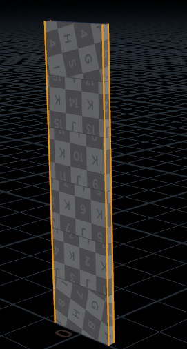
In the new group node we need to select the vertical edges:
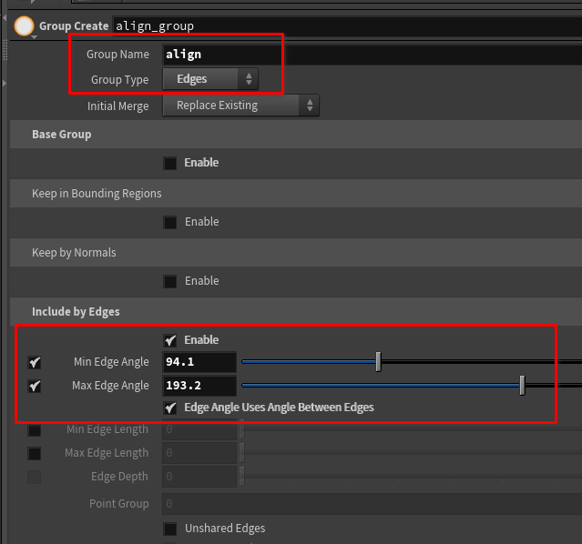
set the group name to align.
Then enable include by edges and use the min and max edge angles until you select the vertical edges.
We will use these to align and rotate our UVs in the same direction.
This alignment will help us for texturing, maybe we want it to be a wood bookshelf and we want the grains to all be in the correct direction.
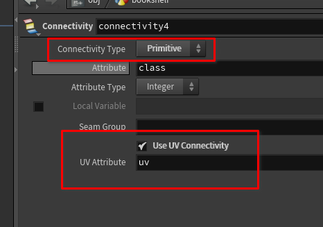
Now let’s setup the loop to run over our UVs.
in the connectivity node set it primitive and the attribute type to integer then toggle on the use UV connectivity and make sure the uv attribute is uv
Now we need to add another uvflatten node, but this time inside the loop.